This is part one of Control Rapiro with Mobile Phone Tutorial. I will show you how to connect Rapiro to RedBearLab BLE Nano Board and use test code to test the connection. If you have successfully connected them, you can go to part two.
Parts Need:
- Rapiro

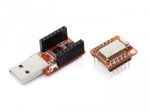
- RedBearLab BLE Nano and MK20 USB Board (we will use MK20 USB to upload the firmware to BLE nano board)
- Four Female/Male Jumper wires.

Preparation:
First, we will use Rapiro‘s standard firmware to control the Robot. The original firmware has defined 10 different actions for Rapiro.
I assume that you have successfully installed driver and upload the standard firmware to Rapiro. If you have not, please follow this instruction
Installing drivers for Rapiro board (Arduino compatible servo motor controller board) to install the servo driver and download the standard firmware (https://github.com/Ishiwatari/RAPIRO/blob/master/RAPIRO_ver0_0/RAPIRO_ver0_0.ino) and use Arduino IDE to upload the firmware to Rapiro.
RedBearLab BLE Nano
There are three options to program your BLE Nano with MK20 USB Board. Since I will be using Arduino IDE, I will write Arduino compatible program for BLE Nano. Of course, you can also program it with Nordic nRF51822 BLE SDK or mbed’s Bluetooth Low Energy API. For more information, please refer to RedBearLab’s instructions.
To program BLE Nano with Arduino IDE , you will need to install RedBearLab nRF51822 add-on to Arduino IDE in order to support nRF51822 development board. If you have not done this step, please follow the instruction (http://redbearlab.com/getting-started-nrf51822) on RedBearLab‘s website and install the add-on to your Arduino Library.
Hardware connection:
Assume that you have already setup the software for development. Now we will connect the Rapiro‘s controller board and BLE Nano together. On Rapiro‘s controller board, there are connection pins (JP5) for connecting Raspberry Pi through serial communication. Serial communication allows you to let two devices to talk to each other through RX/TX pin.
Instead of using Raspberry Pi, we will connect BLE Nano and have it talk to Rapiro‘s controller board through Serial communication.
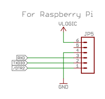
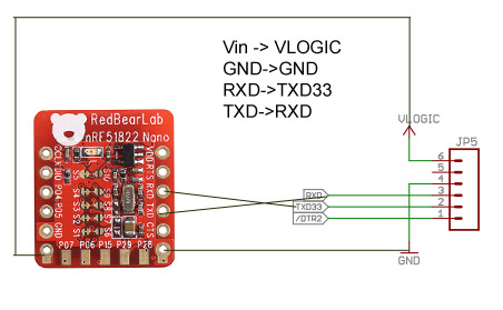
JP5‘s schematic
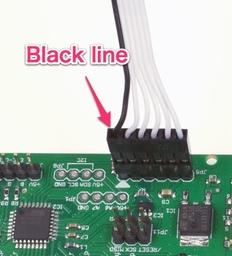
If you are using the 6-pole cable which comes with Rapiro kit, then connect Rapiro controller board like the picture below. Black cable is connected to Pin 1 (/DTR2) on schematic. Pin 2 is TX pin. Pin 3 is RX Pin, Pin 4 is ground. no connection for pin 5. Pin 6 is V pin, which can use as power source to BLE Nano board.
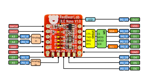
BLE Nano Pinout
We will only use 4 pins on BLE Nano board: VIN, D0, D1, and GND. If you have program Arduino UNO before, you should know that D0 is RX pin and D1 is TX pin on Arduino.
Wiring them together
To create a Serial communication to Rapiro controller board, connect the jumper cable from BLE Nano to Rapiro as the table below. Don’t connect yet because we will upload the test program to BLE Nano first through MK20 USB. Connect them after you have uploaded the program!
| Rapiro Contoller Board | RedBearLab BLE Nano | |
| Pin 6 Vlogic | -> | VIN (Warning: not VDO pin!) |
| Pin 2 (TX) | -> | D1 (RXD) |
| Pin 3 (RX) | -> | D0 (TXD) |
| Pin 4 (GND) | -> | GND |
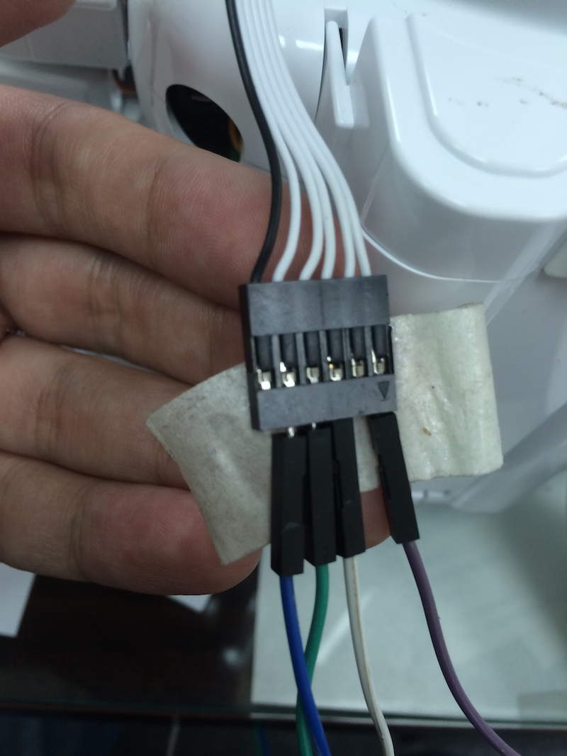
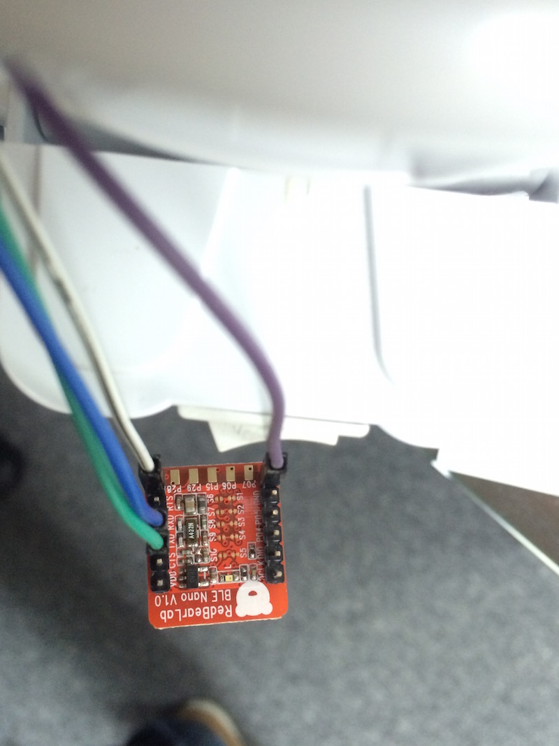
Now connect the 6-pole cable comes with Rapiro kit to the jumper wires. Mark down the color for each wire where you connected to. There is a arrow on the 6-pole cable connector. That is Pin 6 VLogic. In this case, I have chosen purple wire for VLogic, White/black wire for GND, green wire for Pin 4 RX, and blue wire for Pin 2 TX. It will be better if using a tape to secure the connection.
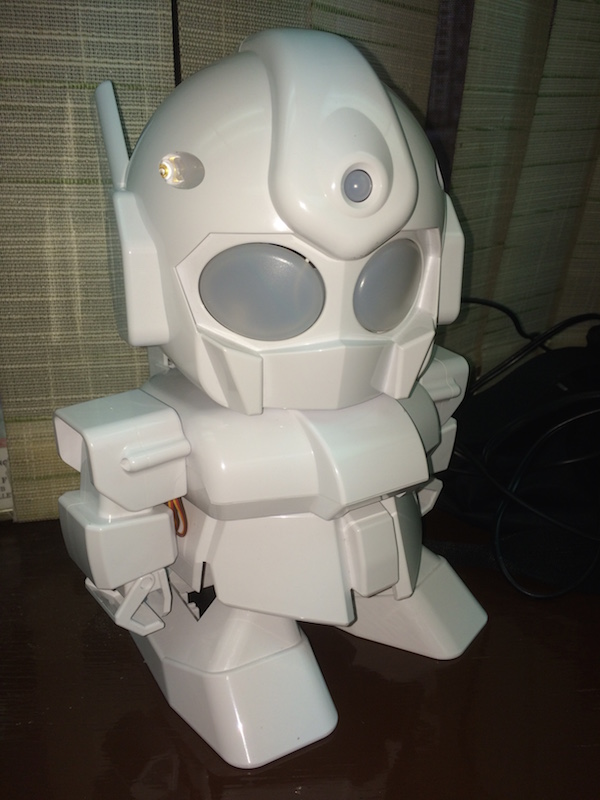
Now have other side of jumper cable and put it outside of Rapiro‘s head.

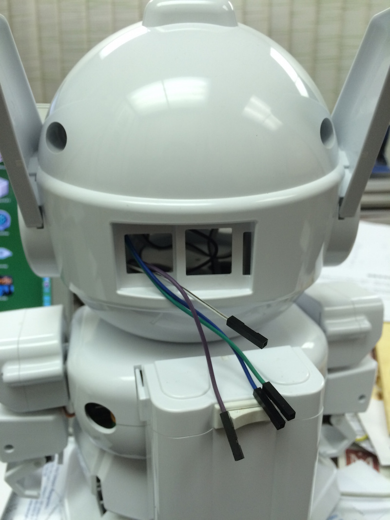
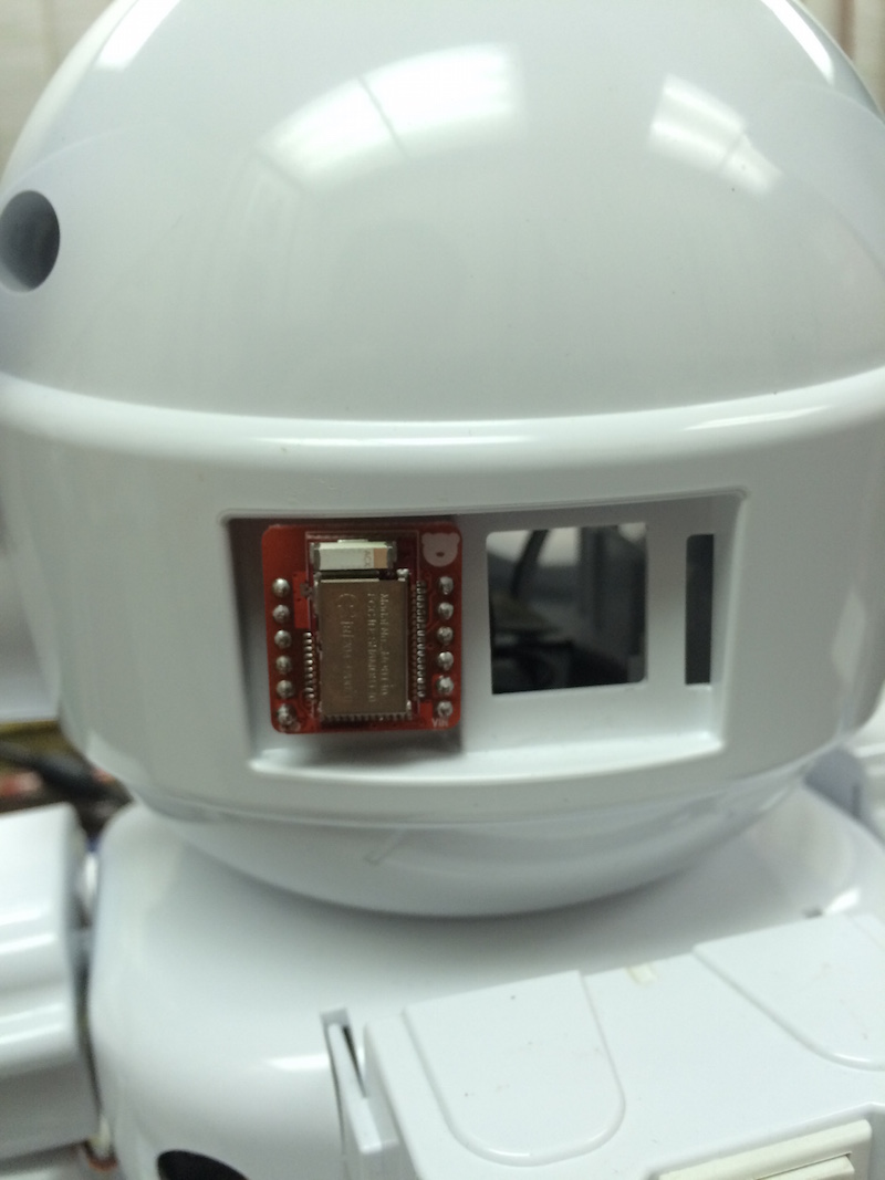
Make sure you remember what colors you have chosen for the connections. In my case, from Rapiro to BLE Nano: Vlogic to Vin (purple wire), GND to GND (white/black), TX to RX (blue), and RX to TX (green). After this, you can place your BLE Nano like the picture below.
Now ready to test the connection.
Test Program
I have created a simple program to test the connection. This program will send couple command from BLE Nano to Rapiro through Serial communication. This program has nothing to do with BLE yet, but it will show you how to talk to Rapiro with BLE Nano.
Here are what the test program will do:
- #M1 will move Forward for about 5 second.
- #M2 will move Backword for about 5 second.
- #M0 stop and back to initial position.
- #M6 Wave right hand for 3 second.
- #M8 Wave left hand for 3 second.
- #M5 wave both hands for 3 second.
- #M0 stop and back to initial position.
#M(number) are standard commands for Rapiro. You can find the command list here: http://wiki.rapiro.com/page/serial-command/
Get the test program from Github: https://github.com/sunnycyk/rapiro_test_program/blob/master/rapiro_test_program.ino
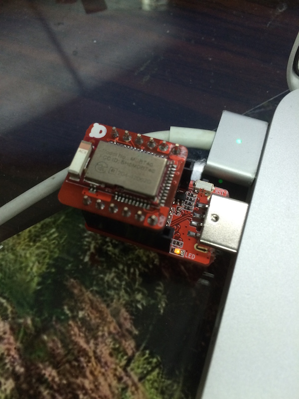
Connect your BLE Nano to your computer with MK20 USB Board.
Copy and Paste the code into Arduino IDE.
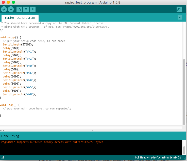
Upload the test program to BLE Nano.
When upload is done, remove BLE Nano from MK20 USB Board.
Connect to Rapiro controller board like the instruction in the last section.
If everything is right, then Rapiro will perform some action like this video.
Conclusion
At the point, you have successfully connected Rapiro to RedBearLab BLE Nano Board! In second part of the tutorial, you will learn how to control Rapiro with mobile phone.
Comments
3 responses to “Control Rapiro with Mobile Phone Part 1”
[…] Part 1: Connect RedBearLab BLE Nano to Rapiro […]
[…] This is part two of Control Rapiro with Mobile Phone tutorial. For information how to connect RedBearLab BLE Nano and Rapiro, you can find in Part one of the tutorial. […]
[…] Please take a look of Control Rapiro with Mobile Device Part 1 […]